


Hydraulic System for Tooling Fixtures
A hydraulic system for tooling fixtures adopts hydraulic transmission technology with pressure oil as the working medium to drive actuators such as hydraulic cylinders. It realizes automatic positioni...
Hydraulic System for Tooling Fixtures
1. Definition
A hydraulic system for tooling fixtures adopts hydraulic transmission technology with pressure oil as the working medium to drive actuators such as hydraulic cylinders. It realizes automatic positioning, supporting and clamping of workpieces. Replacing traditional manual bolt and pressure plate clamping methods, it greatly boosts production efficiency and automation level.
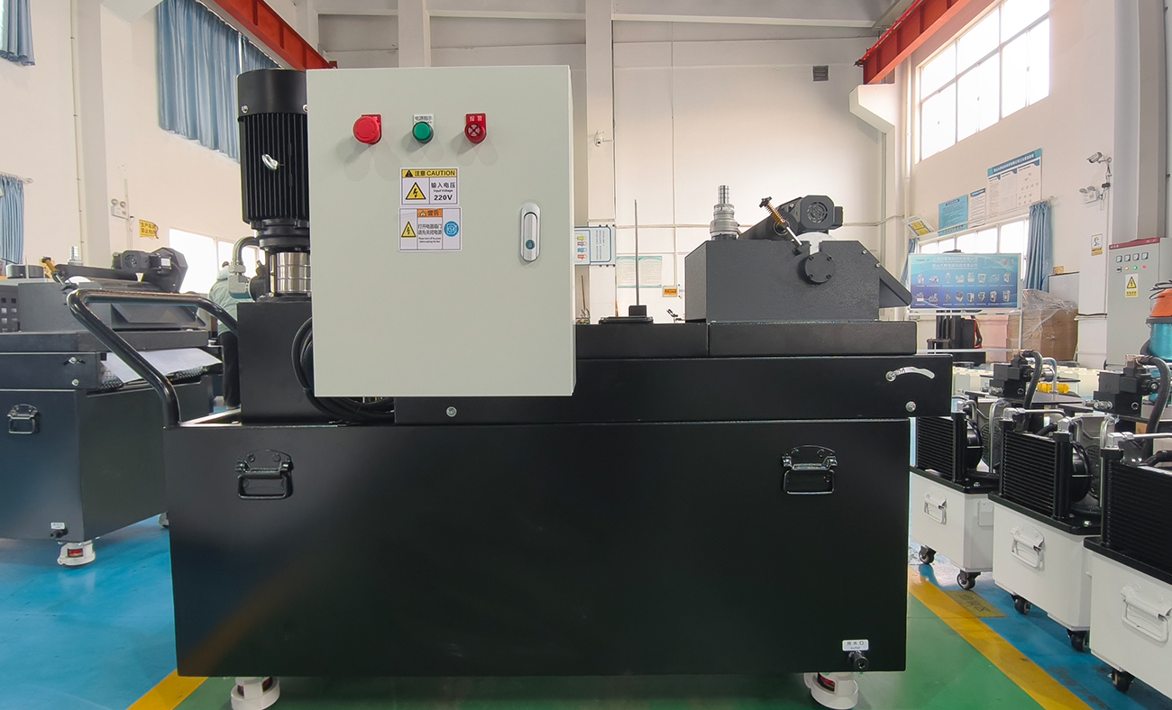
2. Core System Components
Power Components (Hydraulic Power Unit)
Electric motor: Provides prime power.
Hydraulic pump: Converts mechanical energy from the motor into pressure energy of hydraulic oil, serving as the core of the system.
Oil tank: Stores hydraulic oil, and functions for heat dissipation, impurity sedimentation and air separation.
Oil filter: Keeps hydraulic oil clean, which is essential for system reliability and service life.
Control Components (Hydraulic Valves)
Pressure control valve (relief valve): Sets the maximum operating pressure of the system and provides overpressure protection.
Directional control valve (solenoid directional valve): Changes the flow direction of hydraulic oil to control the extension (clamping) and retraction (releasing) of hydraulic cylinders, the key to automatic cycle operation.
Flow control valve (throttle valve): Regulates oil flow into the cylinder to adjust clamping and releasing speed.
Hydraulic lock (hydraulic control check valve): A critical component. It locks the oil circuit after clamping to maintain constant clamping force against external force or system pressure fluctuation, ensuring operational safety.
Pressure reducing valve: Supplies stable pressure lower than the main system pressure for individual circuits when different clamping forces are required.
Actuators
Hydraulic cylinder: Converts hydraulic energy into linear mechanical force to drive clamping mechanisms directly. Common types include double-acting cylinders (pressurized at both ports) and single-acting cylinders (normally spring-returned).
Hydraulic chuck / hydraulic vice: Specialized fixtures integrated with hydraulic cylinders.
Auxiliary Components
Pipelines and fittings: Connect all components and deliver hydraulic oil.
Pressure gauge: Displays real-time system pressure.
Pressure switch: Detects pressure signals and transmits electrical signals to PLC or machine tool CNC when reaching the set value. It enables interlock logic to ensure machining starts only after workpiece clamping is completed.
Working Medium
Hydraulic oil: Transmits power, and provides lubrication, cooling and anti-rust protection.
3. Working Principle & Operation Cycle
Start-up: The motor drives the hydraulic pump, which draws and pressurizes oil from the tank.
Unloading: When idle, the directional valve stays at the neutral position. Oil discharged by the pump returns directly to the tank via the relief valve or neutral valve position, maintaining low system pressure to save energy and reduce heat generation.
Clamping: Upon receiving signals from PLC or manual operation, the solenoid directional valve switches position. Pressurized oil enters the rodless chamber of the cylinder to extend the piston rod and clamp the workpiece.
Pressure holding and locking: System pressure rises after clamping. The hydraulic lock closes to prevent oil backflow. Meanwhile, the pressure switch sends a signal to the machine tool to permit machining.
Machining: The machine tool performs cutting, welding and other processes.
Releasing: After machining, the PLC sends a command to reverse the solenoid valve. Pressurized oil flows into the rod chamber, opening the hydraulic lock and retracting the piston rod to release the workpiece.
Workpiece replacement: Operators unload the finished workpiece and load a new one for the next cycle.
4. Main Advantages
High and stable clamping force: Hydraulic systems deliver powerful and steady force with no impact during operation.
Easy automation: Perfectly compatible with PLC, sensors and other electrical control systems, it serves as the foundation for intelligent manufacturing and Flexible Manufacturing Cells/Systems (FMC/FMS).
Synchronous control for multiple points and forces: One hydraulic power unit can drive dozens or even hundreds of clamping points simultaneously. Pressure reducing valves enable precise adjustment of clamping force at different positions.
Compact structure: Hydraulic components feature small size, light weight and flexible layout under the same power output.
High safety and reliability: Equipped with overload protection via relief valves, and the hydraulic lock ensures long-term stable pressure holding.
5. Application Scenarios
Machining: Fixtures for machining centers, CNC milling machines and lathes, including 4-axis/5-axis rotary table fixtures and hydraulic vices.
Welding production lines: Body-in-white welding fixtures for accurate clamping of steel plates.
Assembly lines: Provides compression force for press-fitting, riveting and other stations.
Testing tooling: Firmly fixes workpieces during measurement.
6. Design Considerations
Clamping force calculation: Calculate required clamping force precisely based on cutting force, workpiece weight and inertia force, which is the fundamental basis for cylinder sizing and system pressure setting.
Priority on safety: Adopt safety circuits such as spring-clamp and hydraulic-release design to keep fixtures clamped in case of power failure or pipe rupture and prevent workpieces from flying out.
Energy saving & heat control: For applications with long pressure holding time, install accumulators for pressure compensation or use proportional variable pumps to reduce energy loss and oil temperature rise caused by long-time high-pressure overflow.
Maintainability: Design the system for convenient air venting, pressure testing, filter replacement and routine maintenance.
7. Common Faults & Troubleshooting
Insufficient clamping force: Improperly set relief valve pressure, internal leakage of hydraulic cylinder, or degraded pump efficiency.
No movement: Motor failure, burnt solenoid coil, stuck valve spool or blocked pressure pipeline.
Slow movement: Insufficient pump flow, clogged filter or excessively high oil viscosity.
Pressure loss during holding: Malfunction of hydraulic lock, damaged cylinder seals or leakage at pipeline joints.
Need a customized digital strategy?
Speak with our system architects about integrating Industry 4.0 into your existing infrastructure.
