English Translation (Professional Hydraulic Engineering Version)
Hydraulic system overheating falls into two categories by cause: overheating arising from design defects, and overheating caused by faulty hydraulic components or improper operation. Correspondingly, troubleshooting methods differ for each category.
1. Overheating Caused by Improper Design and Troubleshooting Solutions
(1) Improper selection of hydraulic oil grade
Improper hydraulic oil selection may lead to system overheating. The system runs normally at low oil temperatures, yet after prolonged operation, the oil temperature rises and oil viscosity drops, resulting in increased internal leakage. Higher leakage further pushes up oil temperature, creating a vicious cycle.
Solution: Select hydraulic oil with appropriate viscosity according to the system load and normal operating temperature requirements.
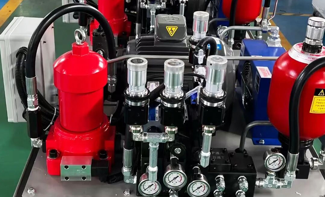
(2) Unreasonable fuel tank design reducing heat dissipation
A hydraulic oil tank mainly stores fluid, and also functions for heat dissipation, impurity sedimentation and water separation. Defective tank design manifests in two aspects:
First, insufficient tank volume. As a mobile hydraulic device, a concrete pump generally adopts a tank volume roughly equal to the flow rate of the hydraulic pump, leading to limited heat dissipation area and oil storage capacity.
Second, flawed structural design. The suction and return pipe orifices are placed too close with no baffle in between. This shortens the cooling circulation and impurity sedimentation path of hydraulic oil. In extreme cases, most return oil flows directly into the suction pipe, impairing heat dissipation and raising oil temperature.
Solution: Increase the tank volume appropriately to 1.25~1.5 times the pump flow rate (Q). Widen the distance between suction and return pipe orifices and install baffles between them to guarantee adequate heat dissipation capacity.
(3) Insufficient cooling flow and improper cooler installation
Concrete pumps adopt air cooling or water cooling, with air cooling being the mainstream choice. Due to pressure resistance requirements, some coolers are installed on the oil circuit of the mixing system, which only cools the hydraulic oil for this subsystem. The low flow rate of the mixing system results in poor overall cooling performance and system overheating.
Adopt an independent cooling circuit to improve cooling efficiency.
Mount the cooler on the main pump oil circuit to increase cooling flow. Two key points need attention:
The cooling fan must maintain a proper rotating speed; low speed will degrade cooling performance. The fan can be driven by an electric motor, or a low-pressure drive motor can be fitted on the main circuit to match rotating speed with cooling flow. This also mitigates the impact of pressure surges in the main circuit on the cooler’s pressure resistance.
If using an electrically driven fan, install a low-pressure overflow relief valve or check valve in parallel with the cooler on the oil circuit to provide overpressure protection against main circuit pressure shocks.
(4) Improper selection of hydraulic components
The hydraulic system of a concrete pump is a high-pressure and high-flow system. If directional valves, overflow valves, sequence valves and other key components are mismatched for the high flow demand, excessive fluid velocity across valve ports will cause substantial pressure loss and temperature rise.
Solution: Select components strictly based on the maximum working pressure, maximum flow rate and regulating range of pressure and flow. Minimize pressure loss across valves to avoid overheating caused by improperly sized components.
(5) Defective pipeline design and installation
Pipeline design and installation are critical. Pipe diameters shall be determined strictly in accordance with working pressure and flow rate. Undersized pipes lead to excessive flow velocity and severe pressure loss, converting pressure energy into heat. In addition, avoid densely arranged pipelines and sharp bends during installation, which hinder natural heat dissipation and cause local pressure loss and overheating.
2. Overheating Caused by Improper Operation or Component Failures and Troubleshooting Solutions
(1) Excessively low oil level in the tank
Monitor the hydraulic oil level regularly during operation and keep it within the specified range to ensure heat dissipation. Top up oil immediately once the level drops below the minimum mark.
(2) Deteriorated cooling performance of the cooler
a) Internal blockage or surface contamination
Blockages inside the cooler or dirt on its surface will actuate safety devices, reduce flow capacity and heat exchange efficiency. Poor ventilation also weakens cooling performance.
Solution: Inspect and clear blockages regularly, and remove surface dirt routinely to keep the cooler unobstructed and clean.
b) Incorrect cracking pressure of safety valves or check valves
If the cracking pressure of protective devices is set below the standard value, the valves will open abnormally even when the cooler is unblocked, resulting in overflow and reduced cooling flow.
Solution: Calibrate the cracking pressure to the specified value before commissioning, and conduct regular inspection and recalibration during operation.
(3) Improper pressure adjustment of the hydraulic system
Safety valves, overflow valves and sequence valves are essential for normal operation.
Underset pressure of safety valves causes frequent valve opening and overflow loss, leading to overheating.
Overset pressure increases internal leakage and further raises temperature.
Solution: Calculate and adjust valve pressure properly according to system load, to keep the system operating within the rated pressure range.
For a closed-loop main circuit of the pumping system, a heat exchange circuit is mandatory. Special attention shall be paid to the setting of the overflow valve in this circuit:
The recommended setting pressure for the overflow valve in the heat exchange circuit is 1.0~1.5 MPa, and the working pressure of the oil replenishment circuit for the pumping system is 2.5 MPa.